FAB ISP
For this weeks assignment we had to produce a In-System Programmer (ISP) which we will be using for the rest of the class to flash other electronics. For this I learned how to use the Roland Modella CNC machine and how to properly solder surface mount components.
Milling
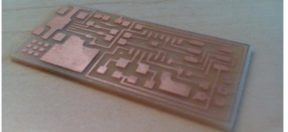
To machine the PCB I used the Roland Modella CNC machine with the FAB modules. To position and setup the machine I undertook the following steps:
1) - Place the PCB on the bed using double sided tape.
2) - Press down firmly ensuring that it's level
3) - Select the required bit (1/64" - Track, 1/32" - Outline)
4) - Using the Allen key release the bit
5) - Replace bit and allow it to sit on the surface of the PCB
6) - Lock in the bit using the Allen Key
7) - Machine following the FAB Module instructions
FAB Modules Setup
To machine the board I used the FAB module with standard PNG image files to which defined both the track and outline of the board. To Machine the board I undertook the following steps:
1) - Launch the FAB Module and select PNG to Modella
2) - Load the PNG image for the track or outline
3) - Select the bit size from type drop down box (1/64" - Track, 1/32" - Outline)
4) - Set the X/Y home position of the PCB
5) - Click move to xmin/ymin to check location
6) - Set the Z axis value by releasing the bit
7) - Click make Path & make RML
8) - Click send it to begin machining
9) - Repeat steps 2, 3, 7 & 8 to change from track to path
Assembling
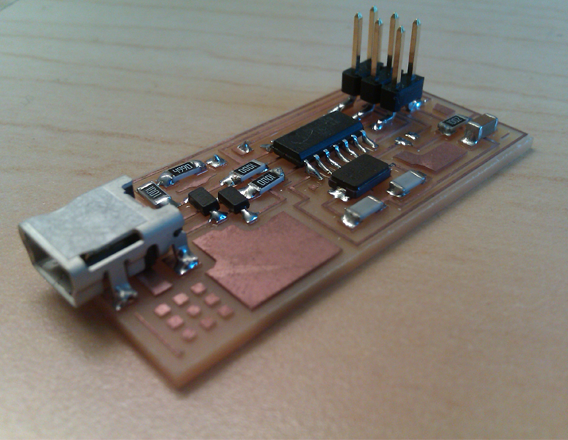
Once the PCB has been machined you will need to stuff it with the various components. These are surface mount devices and so you will need some tweezers and a steady hand.
1) - Start from the inside and work out
2) - Choice components from
3) - Place solder on the board then resolder this for the first connection
4) - If you use too much solder make use of the Desoldering braid (USB Connector)
5) - The Iron should be set to around 65/70
Tips/Advice
When machining the board if the PCB does not sit level on the bed then you will end up with badly milled paths that won't work.. To overcome this if you can't see what's obstructing the board you can adjust the 2D z (mm) value which will ensure that a deeper cut is made. This isn't an idea solution but will ensure that the PCB machines with working tracks.

Machined PCB

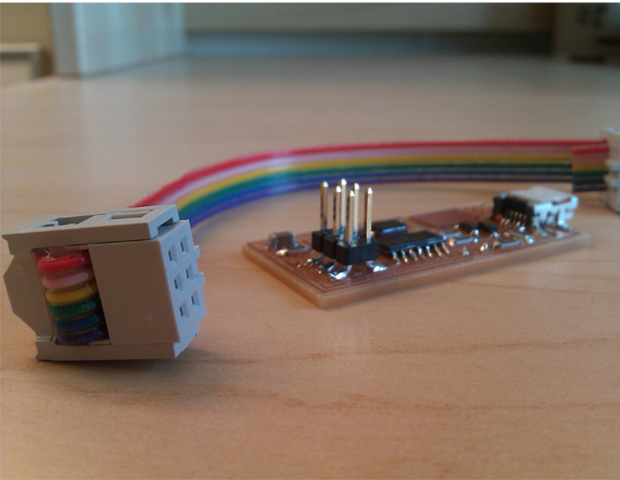
Final FAB ISP
