Output Devices
This week I decided to try and build an LED matrix and so started by looking at shift registers and increasing the number of digital pins.
Reverse Bias/Direct Measure
Having previously seen this paper on low-cost led sensing I decided to try and implement it and make a matrix input/output device.
I first tried with the reverse bias approach which measures the amount of time it takes for led to dissipate its charge. I found this took too long between cycles and so created a flicker effect when trying to produce a constant light source.
The second approach I used was to directly measure each row of the matrix through an ADC. Due to the photoelectric effect incoming light causes electrons to flow and so it's possible to measure the voltage generated within the matrix. This reading is therefore proportional to the current light levels and so it's possible to create a proximity sensor as shown in the video opposite.
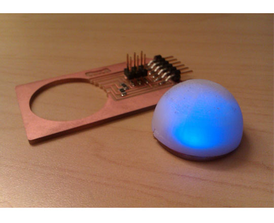
PWM
Continuing with last weeks projects I reprinted the dome for the voxel PCB and changed the previous PWM code to ensure it correctly fades in and out of the selected colour. The improved version can be seen in the video opposite.
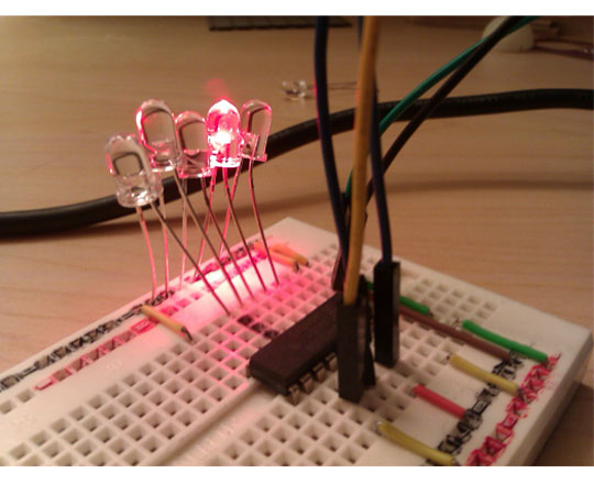
Shift Register Testing
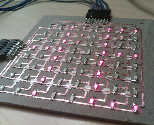
Vinyl Cut Matrix
Scrolling Text
Direct Measure Sensing