Shopbot
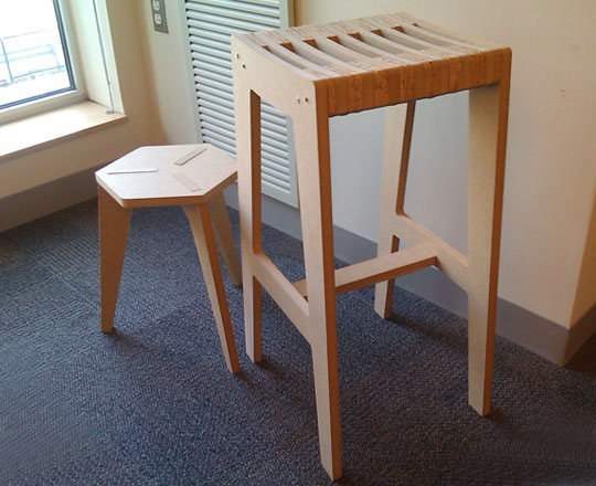
This weeks assignment is make something BIG and so I decided to build some new furniture for my room. For this I have made two designs a simple three legged push fit stool and a larger breakfast bar type stool.
Design
Both of these were designed using Solidworks and then exported as DXF files for use with the shopbot. The image opposite shows the original CAD renderings of the designs as completed with solidworks in built photoview 360 software.
Imperial Measurements
If like myself you are struggling to let go of the metric system and don't want your designs to be 25 times larger then you expect, simply follow the instructions below...
All the machines I have used so far have been setup for use with the imperial system and so the easiest approach I have found is to convert the units on your solidworks drawing just before you export it.
1) Clicks 'Options' from the top toolbar
2) Select 'Document Properties' then 'Units'
3) Change from IPS to MMGS (Solidworks will automatically update)
4) Export to DXF as normal
Solidworks DXF Missing Lines!
When exporting solidwork designs from a 2D diagram it can sometimes ignore any curved lines within the diagram. If this happens do the following:
1) Select the sketch you wish to export
2) Extrude the sketch by a few mm
3) Change the viewpoint so that you re parallel to the sketch
4) Click 'Save As' and select DXF
5) Within the export options select 'From Face'
This will then output from the faces ensuring that all curved lines are created.
Notes
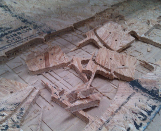
Be careful when positioning the components to ensure that the tool paths have adequate space not to interfere with each other. In the picture opposite
If you are starting this project book the Shopbot NOW. It is heavily overbooked and it will take twice as long as you expect..
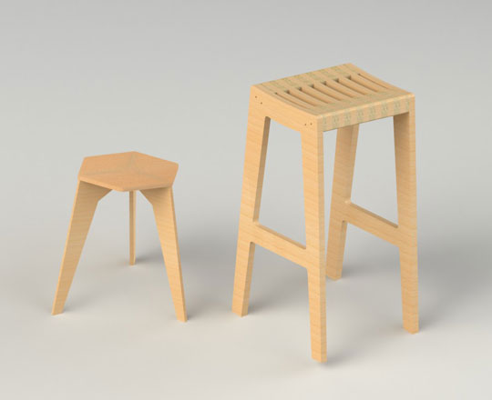
Initial Designs
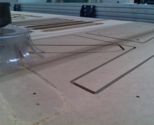
Shopbot Milling
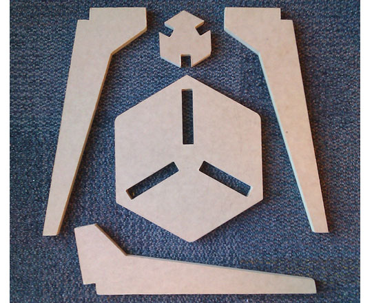
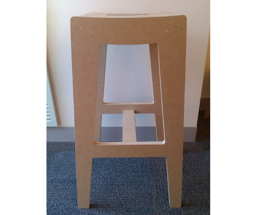
Stool parts
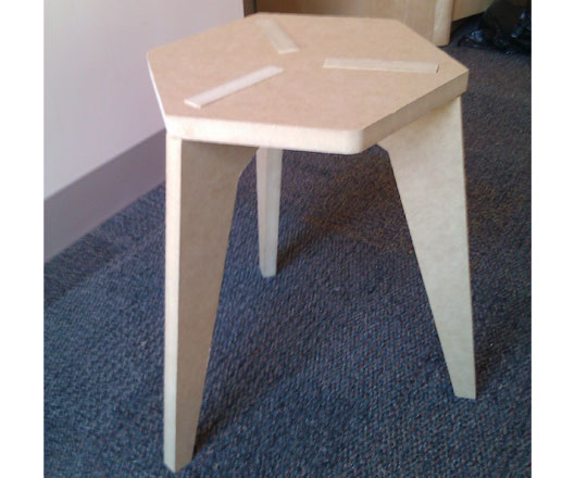
Final Press Fit Stool
Failed Tool Path
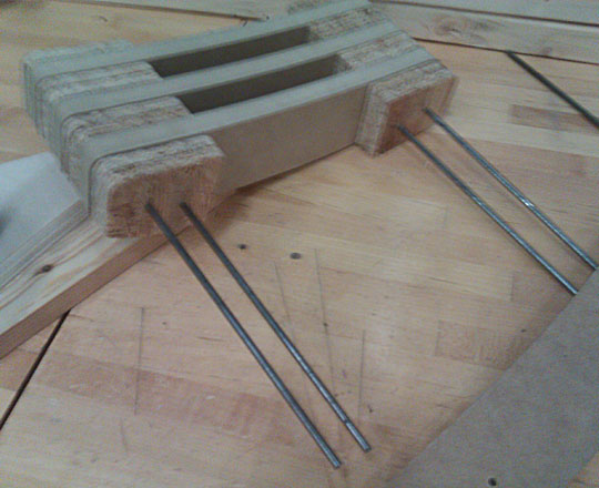
Seat Steel Support
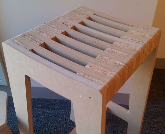
OSB & MDF Seat
Stool Profile